C-DReAM FR1 COEX [SC1-SC6] templates provides a 3GPP RAN4 is working on an NTN coexistence study in frequency bands around 2GHz. This involves producing system level simulations with regards to Terrestrial (TN) and Non-Terrestrial Network (NTN) co-existence within adjacent frequency bands. Template is implemented by the C-DReAM simulator. The scenarios follow approach defined in 3GPP TR38.863 and the simulator has been calibrated with the TN and NTN calibration scenarios.
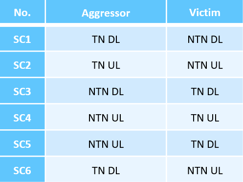
The six FR1 3GPP adjacent channel co-existence scenarios are shown in the table above. Only one ACI configuration per scenario / template is enabled at the time.
Essential pre-conditions
NTN satellite with 1 beam and 1-tier FR3 wrap-around (6 beams generating co-channel interference)
TN network with 7 macro sites with 3 sectors each (21 cells total)
10 UEs per TN cell area = 210 in total
50 NTN UEs on the edge of TN; Default isolation distance of 2 * ISD (=1500m) in Urban scenarios, no isolation in Rural scenarios.
TN interference scaling enabled (in cases 2 and 6 where NTN UL is the victim), assuming 20% TN area coverage
Full buffer traffic
Configurable options
NTN orbit & TN scenario & Isolation distance combinations available
LEO600_Urban_Default
LEO600_Urban_NoIsolation
LEO600_Urban_InCluster
LEO600_Rural_Default
LEO600_Rural_InCluster
LEO1200_Urban_Default
LEO1200_Urban_NoIsolation
LEO1200_Urban_InCluster
LEO1200_Rural_Default
LEO1200_Rural_InCluster
GEO_Urban_Default
GEO_Urban_NoIsolation
GEO_Urban_InCluster
GEO_Rural_Default
GEO_Rural_InCluster
GEO45_Urban_Default
GEO45_Urban_NoIsolation
GEO45_Urban_InCluster
GEO45_Rural_Default
GEO45_Rural_InCluster
Adjacent Channel Interference Ratio (ACIR) options
Disabled (mandatory option for throughput and SINR loss figures!)
0, 10, 20, 30, 40 dB
The ACIR is internally by aggressor ACLR and victim ACS parameters. For example 30 dB ACIR is achieved with ACS 33 dB and ACLR 33.02062 dB configuration which leads to the 30 dB total ACIR. The extra adjacent channel interference attenuation is full controlled by the ACIR, and guard band between the carriers has no impact. Also, the ACIR is the same for all aggressor and victim PRBs, thus scheduling in frequency has no impact on the ACI.
In order to get throughput and SINR loss figures one must have ACIR Disabled and at least one other ACIR configuration selected! The image below shows how one can verify in Phase 3 Launch view that these post-processing figures are enabled. The SINR loss for one ACIR value is simply the difference of SINR compared to ACIR disabled case. Two figures per category are given: average loss and 5% loss. The 5% loss numbers might unreliable be unless enough simulations are run as only 1/20 (~UEs) of the samples are effective.
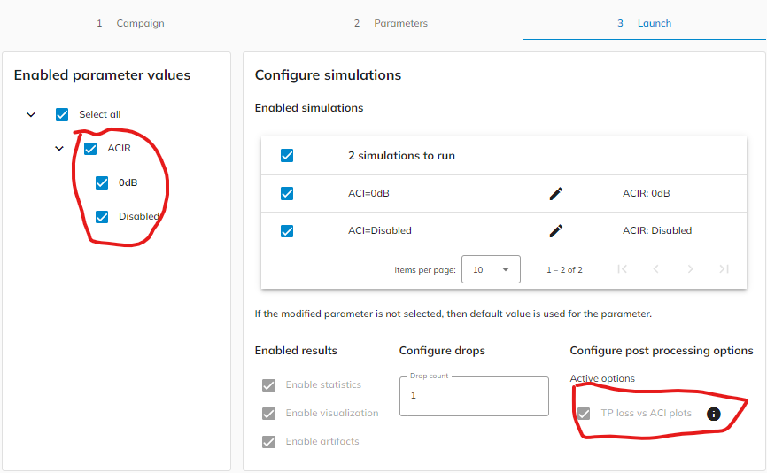
Phase 3 of starting campaign and essential points to get TP and SINR loss figures.
NTN UE Layouts
In the figures below three different options for NTN UE placement are shown. The 2 x ISD isolation distance option is only applicable for Urban deployment and is called Default in the scenario name as it is the option defined for 3GPP scenarios. The NTN UEs are placed on a ring surrounding the TN cluster.
In NoIsolation NTN UE placement option the NTN UEs are on a ring which is next to TN cluster, i.e., the outermost TN UEs can be next to some NTN UE, but no NTN UE is closer to TN gNBs as TN UEs. This is the default option for Rural in 3GPP and also available for Urban.
In InCluster case all NTN UEs are within the TN cluster, but no closer than 250m to any gNB. Available for Rural and Urban TN deployment cases.
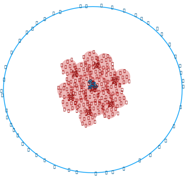
1500m isolation / Default. Urban only. TN read, NTN blue.
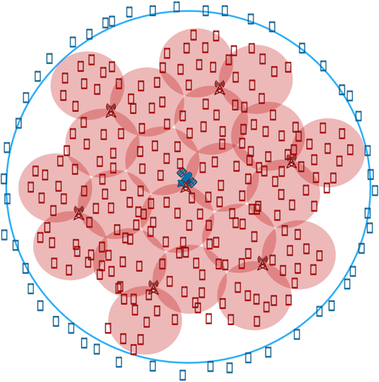
No isolation (Urban) / Default (Rural). TN read, NTN blue.
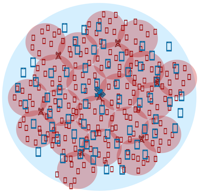
InCluster (Urban and Rural). TN read, NTN blue.
RAN4 Templates
All the templates are identical to each other except on the Adjacent Channel Interference (ACI) configuration. Other channels do not interfere each others.
Scaling factor. The simulated TN network does not cover the whole beam but caused interference has been scaled up assuming there are TN cells on full NTN beam coverage area. Assuming 20% activity factor.
Elevation angle: LEO600, LEO1200 and GEO have 90 degree satellite elevation angle. In the GEO45 the elevation angle is 45 degrees. The scenario elevation angle is calculated at the center of the beam, and thus the actual elevation angle per UE can be slightly different.
RAN4-SC1
Aggressor TN DL. Victim NTN DL.
RAN4-SC2
Aggressor TN UL. Victim NTN UL. ACI scaling enabled.
RAN4-SC3
Aggressor NTN DL. Victim TN DL.
RAN4-SC4
Aggressor NTN UL. Victim TN UL.
RAN4-SC5
Aggressor NTN UL. Victim TN DL.
RAN4-SC6
Aggressor TN DL. Victim NTN UL. ACI scaling enabled.
References
[1] TR38.863, Release 18, Non-terrestrial networks (NTN) related RF and co-existence aspects, 2024.
General C-DReAM Assumptions
Here are general C-DReAM assumptions and features described. Not all of them are applicable to FR1 COEX templates.
C-DReAM is a link budget / capacity level system simulator, i.e. we cannot observe e.g. packet-level statistics, such as delay or jitter.
Traffic is modeled by means of traffic demand in kbps, which is aimed to be offered to the user, either in uplink or downlink.
Configurable NGSO satellite constellations, i.e. number of satellites, orbits, altitudes, etc, are configurable. Geostationary systems, terrestrial networks and hybrid TN/NTN networks are TBA.
Bessel (TR 38.821) based beam patterns either in quasi-earth-fixed (QEF) or earth-moving (EM) configurations..
Stationary user terminals. The terminals are positioned in randomized positions with certain configurable geographical limitations (e.g. continent and country).
Terminals can have either omnidirectional antenna, VSAT or AAS antenna, which is modeled by means of TR 38.811 Bessel model.
5G NR-NTN waveforms (Table 1, 2 or 3) in both downlink and uplink.
Simple fair reference resource management algorithm, i.e. scheduler. Note, the algorithm cannot be currently changed entirely by the user (only within the capabilities of current parameterization), but that requires further development in SimLab and/or C-DReAM simulator.
Configurable options
General C-DReAM configuration options in https://docs.magistersimlab.com/NGSO.html . The available for parameters for COEX templates are described below. Not all of them are available for scenario as enabled link / ACI directions depend on the scenario.
Algorithm
Algorithm module paremeters are specific to TN/NTN. GNB prefix designates TN parameter, without is for NTN.
GNB DL max allocation size in frequency: Maximum resource allocation size for downlink for TN gNB
GNB DL max scheduled users: Maximum number of scheduled users in a time slot on DL for TN gNB.
GNB DL min allocation size in frequency: Minimum resource allocation size for downlink for TN gNB
GNB UL max allocation size in frequency: Maximum resource allocation size for uplink for TN gNB
GNB UL max scheduled users: Maximum number of scheduled users in a time slot on UL for TN gNB.
GNB UL min allocation size in frequency: Minimum resource allocation size for uplink for TN gNB
DL max allocation size in frequency: Maximum resource allocation size for NTN downlink.
DL max scheduled users: Maximum number of scheduled users in a time slot on NTN DL.
DL min allocation size in frequency: Minimum resource allocation size for NTN downlink.
UL max allocation size in frequency: Maximum resource allocation size for NTN uplink.
UL max scheduled users: Maximum number of scheduled users in a time slot on NTN UL.
UL min allocation size in frequency: Minimum resource allocation size for NTN uplink.
Common
The parameters in common module are common to NTN and TN.
DL beam hopping slots: Number of time/beam hopping slots for downlink.
DL frequency slot resolution Hz: The resolution of downlink frequency slots in Hz.
DL frequency slots: Number of frequency slots for downlink.
UL beam hopping slots: Number of time/beam hopping slots for uplink.
UL frequency slot resolution Hz: The resolution of uplink frequency slots in Hz.
UL frequency slots: Number of frequency slots for uplink.
CoverageAreaUtGenerator
NTN UE max height m: NTN UE maximum height in meters
NTN UE min height m: NTN UE minimum height in meters
TN UE minimum distance to TN km: Minimum 2D distance of TN UEs to TN gNBs.
UEs per NTN cell: Number of UEs per NTN cell area.
UEs per TN cell: Number of UEs per TN cell
Linkbudget
The parameters for Linkbudget module are TN/NTN specific. GNB/TN perfix designates TN parameters.
GNB antenna element gain dBi: Antenna element gain assumed for terrestrial gNB.
GNB antenna horizontal elements: No. of horizontal antenna elements assumed for terrestrial gNB.
GNB antenna vertical elements: No. of vertical antenna elements assumed for terrestrial gNB.
GNB noise figure dB: Terrestrial gNB noise figure in dB.
GNB tx power: Terrestrial gNB Tx power. Unit total dBm.
NTN UE noise figure dB: UE antenna noise figure in dB.
NTN UE power control mode: UL power control mode. RAN4 modes refer to TR38.863 with 15 dB and 25 dB SNR target.
NTN UE rx antenna gain dBi: NTN UE Rx antenna peak gain in dBi.
NTN UE tx antenna gain dBi: NTN UE Tx antenna peak gain in dBi.
NTN UE tx power: UE Tx power. Unit is dBm in total.
TN UE antenna horizontal elements: No. horizontal antenna elements assumed for UE using TR38.901 antenna array.
TN UE antenna vertical elements: No. vertical antenna elements assumed for UE using TR38.901 antenna array.
TN UE noise figure dB: UE antenna noise figure in dB.
TN UE tx power: UE Tx power. Unit defined is dBm in total.
TN UE rx antenna gain dBi: UE Rx antenna peak gain per element in dBi
TN UE tx antenna gain dBi: UE Tx antenna peak gain per element in dBi
SimLabVisualizationAdapter
Beam visualization mode: Beam visualization mode. Options: point, polygon or circle. Polygon is most representative, point is fastest.
Variations
ACIR: ACIR selection. For co-existence simulations one must select Disabled and at least one other option to see throughput and SINR degradation compared to reference (ACIR Disabled).
Scenario: Scenario selection. Affecting satellite orbit, elevation angle, NTN UE placement, and TN network.
